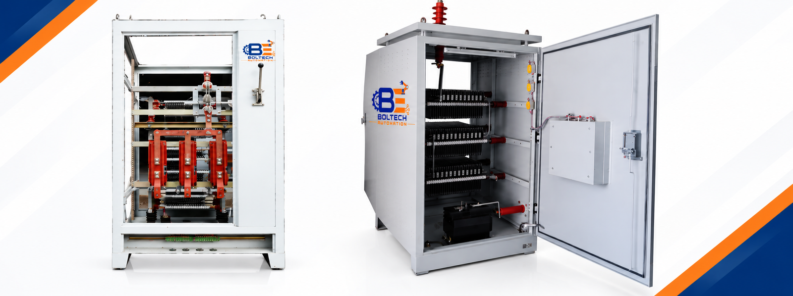
Neutral Grounding Resistor (NGR) Panels feature two main neutral grounding methods: Low Resistance Grounding (LRG) and High Resistance Grounding (HRG). NGR is connected between the transformer neutral and earth to limit earth fault current to a safe value during ground faults.
Features
Two main neutral grounding methods: Low Resistance Grounding (LRG) and High Resistance Grounding (HRG).
NGR is connected between the transformer neutral and earth.
It limits earth fault current to a safe value during ground faults.
Enables quick fault detection and isolation without damaging equipment.
Reduces equipment damage, arc blast risk, and transient over-voltages.
Improves system safety, reliability, and protection during earth faults.
Advantages
Limits earth fault current and protects electrical equipment from damage.
Prevents overheating and reduces mechanical stress on cables, transformers, switchgear, and motors.
Improves personnel safety by minimizing fault energy and arc flash risk.
Helps isolate faults quickly and prevents fault propagation.
Low Resistance Neutral Grounding (LRG)
In a Line-to-Ground (L-G) fault, the protection system trips the circuit to clear the fault.
The Neutral Grounding Resistor (NGR) limits the earth fault current to a safe range of 100 A to 1000 A.
Zero Sequence Current Transformers (ZSCT) and Ground Fault Relays detect the fault and typically operate at 5–20% of the maximum fault current.
LRG resistors are generally designed for 10 seconds duty with a maximum temperature rise of about 760°C.
The selected fault current must be high enough to ensure reliable operation of the ground fault relay.
System Voltage-2.4 kV / 4.16kV/6.9kV / 34.5kV.
NGR Current Rating-100A - 400 A.
High Resistance Neutral Grounding (HRG)
In a Line-to-Ground (L-G) fault, the system gives an alarm but does not trip, ensuring continuous power supply.
HRG is recommended for processes where power interruption is not acceptable.
The Neutral Grounding Resistor (NGR) limits the earth fault current to 5–10 A.
Zero Sequence Current Transformers (ZSCT) and Ground Fault Relays detect the fault and generate an alarm at 10–20% of the maximum fault current.
HRG resistors are designed for continuous duty with a maximum temperature rise of about 375°C.
The selected fault current must be higher than the system’s total charging current to ensure reliable fault detection.
Key Point
Low Resistance Grounding (LRG) is commonly used in medium voltage mine power systems.
The Neutral Grounding Resistor (NGR) limits earth fault current to 25–50 A.
This keeps touch voltage within 100 V or less, improving personnel safety.
The selected NGR current must be higher than the system’s total charging current to ensure reliable earth fault detection.