Get a Quote
Share your requirement and our team will get back to you via email shortly.
Share your requirement and our team will get back to you via email shortly.
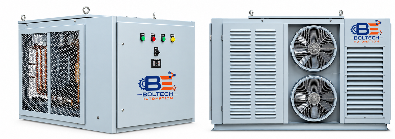
Grid Resistance Starter is engineered for heavy-duty slip ring induction motors. Utilizing high thermal capacity metallic resistance banks (SS410), it ensures smooth, controlled, and stress-free motor acceleration with dust and vermin proof construction.
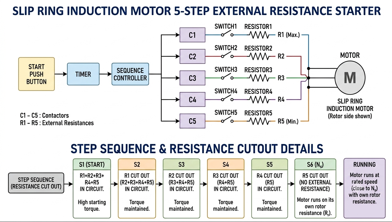
Grid Resistance Starter works on the principle of introducing external resistance into the circuit of a slip ring induction motor during starting. The resistance is reduced in stages as the motor accelerates, providing the required starting torque while limiting starting current.
This ensures smooth and controlled motor acceleration with a predetermined torque profile.
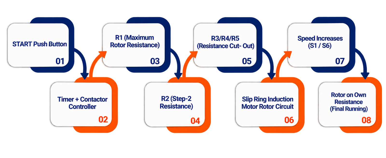
Specific resistance grids are connected in the rotor circuit at predefined motor speeds. The resistance values are calculated in advance according to the required torque at each stage.
Contactors and preset timers control the sequential switching of the resistance grids. At each timer interval, a portion of the rotor resistance is automatically cut off. The entire starting process is fully automatic and operated through a push-button, gradually removing all resistance until the motor reaches its rated speed.