
Get a Quote
Share your requirement and our team will get back to you via email shortly.
Share your requirement and our team will get back to you via email shortly.
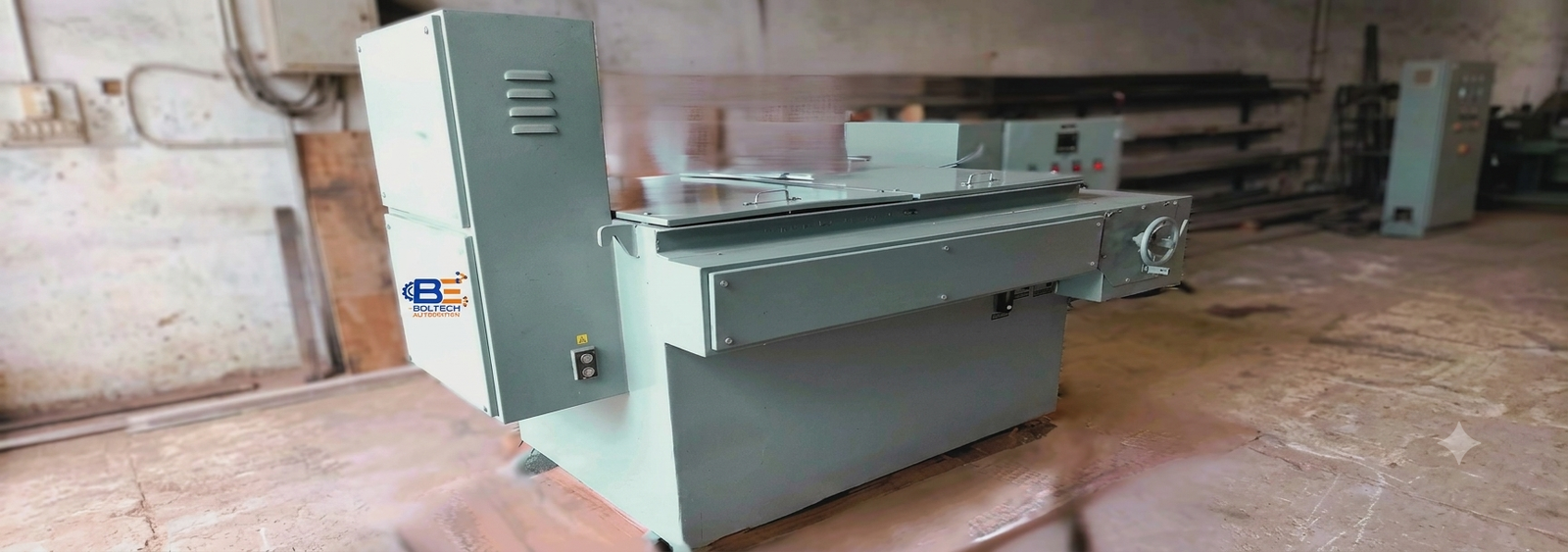
Conventional LRS (Liquid Resistance Starter) is engineered for controlled, smooth starting of large-rated slip-ring induction motors ranging from 100 KW to 8000 KW (and up to 15,000 kW+) at 415V AC / 6.6 / 11 KV ratings. It ensures high starting performance, optimal rotor resistance variation, and stable industrial drive operation.
A Liquid Resistance Starter (LRS) is primarily used for controlling the starting of slip-ring induction motors. During motor starting, the current is generally restricted to a maximum of 250% of the full-load current (FLC). The required initial resistance is selected according to the application to obtain the desired starting torque.
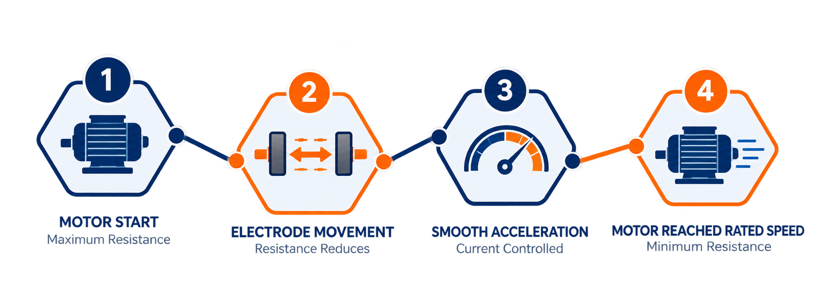
The LRS operates by automatically varying the resistance in the rotor circuit throughout the starting process. This provides optimum starting characteristics and enables the motor to accelerate smoothly and progressively up to full-load speed.
The resistance variation is achieved by moving the electrodes within the electrolyte, which gradually changes the effective resistance of the starter. Once the motor completes its acceleration and reaches the required operating speed, the electrodes are shorted out, allowing the motor to operate under normal running conditions.
The LRS can also be used for speed variation and torque control, depending on the application requirements.
The LRS is equipped with a robust driving mechanism housed inside a mechanism box. It consists of a pilot motor, gearbox, spur gear set, and pinion that transmit motion to the moving electrode assembly through a shaft with a sprocket-and-chain arrangement. The moving electrodes are mounted on a channel supported by rollers, allowing smooth horizontal movement along guide rails.
For maintenance or emergency operation, the motor drive can be disengaged using a declutching mechanism, and the electrodes can be operated manually through a hand wheel. Oil-tight limit switches are provided to accurately stop the movement of the electrode system at the required end positions, ensuring safe and reliable operation.
The control system is housed in a sheet steel control panel with IP54/IP55 protection for reliable industrial operation. The pilot motor is controlled through a Variable Frequency Drive (VFD), allowing smooth adjustment of the main motor acceleration time.
A supervisory timer protects the motor from prolonged starting, while low electrolyte level and high temperature indications with interlocks ensure safe operation. Optional control features can be provided as per customer requirements.
| SN. Index | LRS MODEL Series Type | UPTO KW Kilowatts | UPTO HP Horsepower | Overall Dimensions L x W x H In Cubic mm |
|---|---|---|---|---|
| 1 | LRS-1 | 300 | 400 | 1400 X 1150 X 1225 |
| 2 | LRS-2 | 410 | 550 | 1650 X 1150 X 1225 |
| 3 | LRS-3 | 900 | 1200 | 1650 X 1350 X 1425 |
| 4 | LRS-4 | 1200 | 1600 | 2050 X 1350 X 1425 |
| 5 | LRS-5 | 1700 | 2275 | 2100 X 1600 X 1625 |
| 6 | LRS-6 | 2000 | 2700 | 2600 X 1600 X 1625 |
| 7 | LRS-7 | 2800 | 3750 | 2650 X 1800 X 1925 |
| 8 | LRS-8 | 3200 | 4300 | 3400 X 1800 X 1925 |
| 9 | LRS-9 | 4200 | 5630 | 3250 X 2050 X 2250 |
| 10 | LRS-10 | 5000 | 6700 | 3650 X 2050 X 2250 |
| 11 | LRS-11 | 5600 | 7500 | 3800 X 2100 X 2300 |
| 12 | LRS-12 | 6700 | 9000 | 4300 X 2100 X 2300 |