
Get a Quote
Share your requirement and our team will get back to you via email shortly.
Share your requirement and our team will get back to you via email shortly.
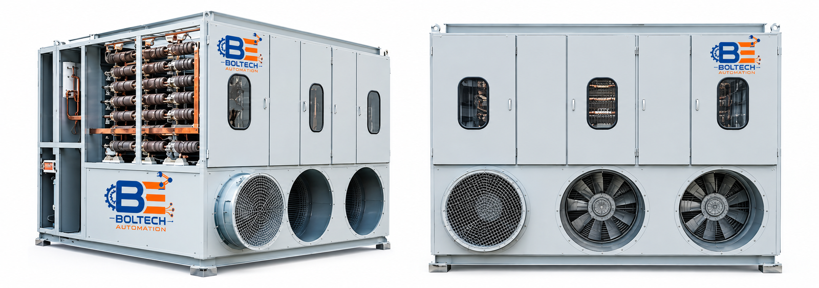
Grid Resistance Regulator (GRR) utilizes forced air-cooled grid resistors to efficiently control the speed of slip ring induction motors. Designed for heavy-duty industrial environments, it delivers reliable performance, excellent energy savings, and smooth speed variations without harmonic generation.
GRR uses forced air-cooled grid resistors to control the speed of a slip ring induction motor. External resistance is inserted into the rotor circuit, which shifts the motor’s torque-speed characteristic toward the left. As a result, the operating point moves to a new stable point at a lower RPM while maintaining the same load torque.
By increasing the external rotor resistance, the motor speed can be smoothly reduced to approximately 50% of its rated speed. This method provides efficient speed control and helps save energy in fan and blower applications.
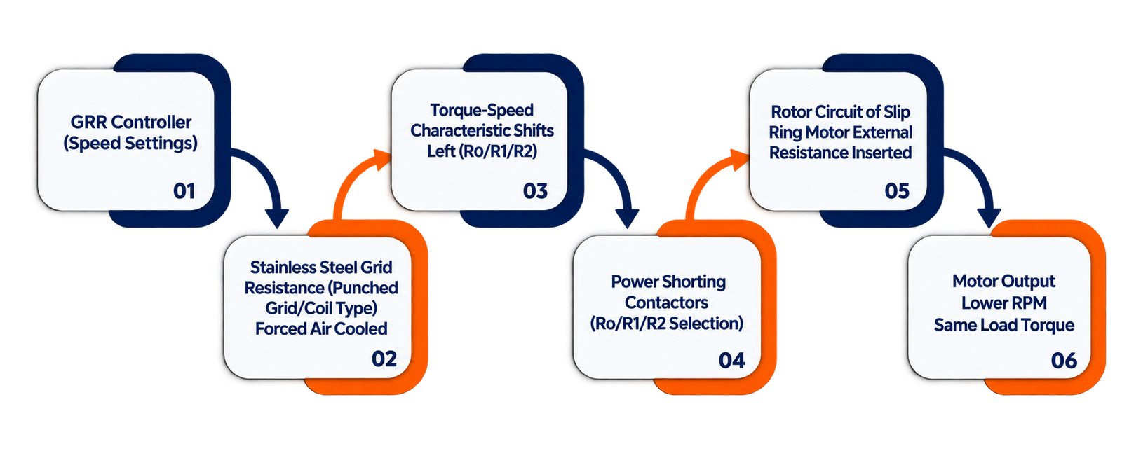
GRR uses stainless steel (SS) metallic resistance elements in punched grid or coil type construction to provide the required resistance in the rotor circuit of a slip ring induction motor. These resistance elements are specially designed and fabricated for continuous duty operation to match the motor ratings.
The resistance is divided into multiple steps for smooth and accurate speed control. Speed is increased or decreased gradually by switching the resistance steps through power shorting contactors, preventing sudden current surges. The speed variation between consecutive steps is typically 1% to 2.5% (or as specified by the customer).
A forced cooling blower is provided inside the resistance chamber to dissipate the heat generated during operation. This maintains stable resistance values, reduces temperature effects, and increases the service life of the resistance elements.